The laser unit 🔗
A few days ago, i opened a broken laser printer to get its laser unit. The printer was a Brother HL2030. I totally forgot to take pictures of the disassembling.
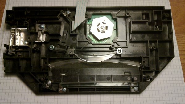
The picture shows the laser unit with already dismounted top cover, laser diode (the laser beam of a laser printer is invisible and extremely dangerous for the human eye!) and controller PCB for the diode.
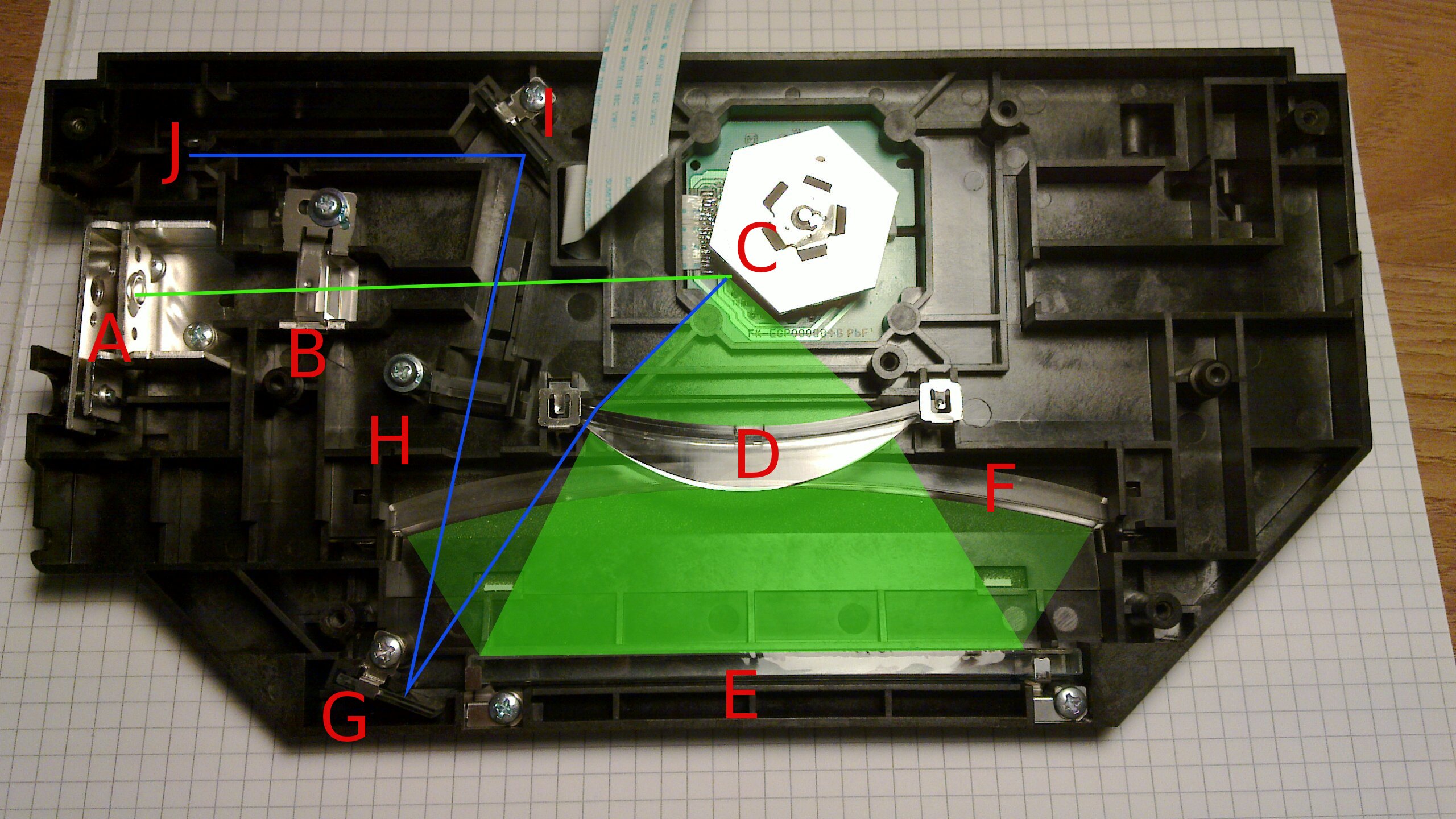
This is the areas the beam would normally cover. Its not very exact, more an assumption but to me it looks right. The beam starts at the laser diode [A] on the left, goes through a lens [B] (i don’t understand the function of this lens at the moment), then it hits the rotating mirror [C], which diffracts the beam. From here i marked the area the beam can hit in light green. The beam goes through a concave lens [D] which spreads the range. Then it gets reflected by a mirror [E] and goes through another concave lense [F]. The last mirror is under the galvanometer. It diverts the beam to the paper.
But there is another three mirrors/lenses. The mirror [G] reflects the beam whenever it has crossed the whole concave lens. From there it goes through a lens [H] which looks like the one [A] the beam passes at the start. Then it gets reflected by a mirror [I] again and hits finally a phototsensor [J].
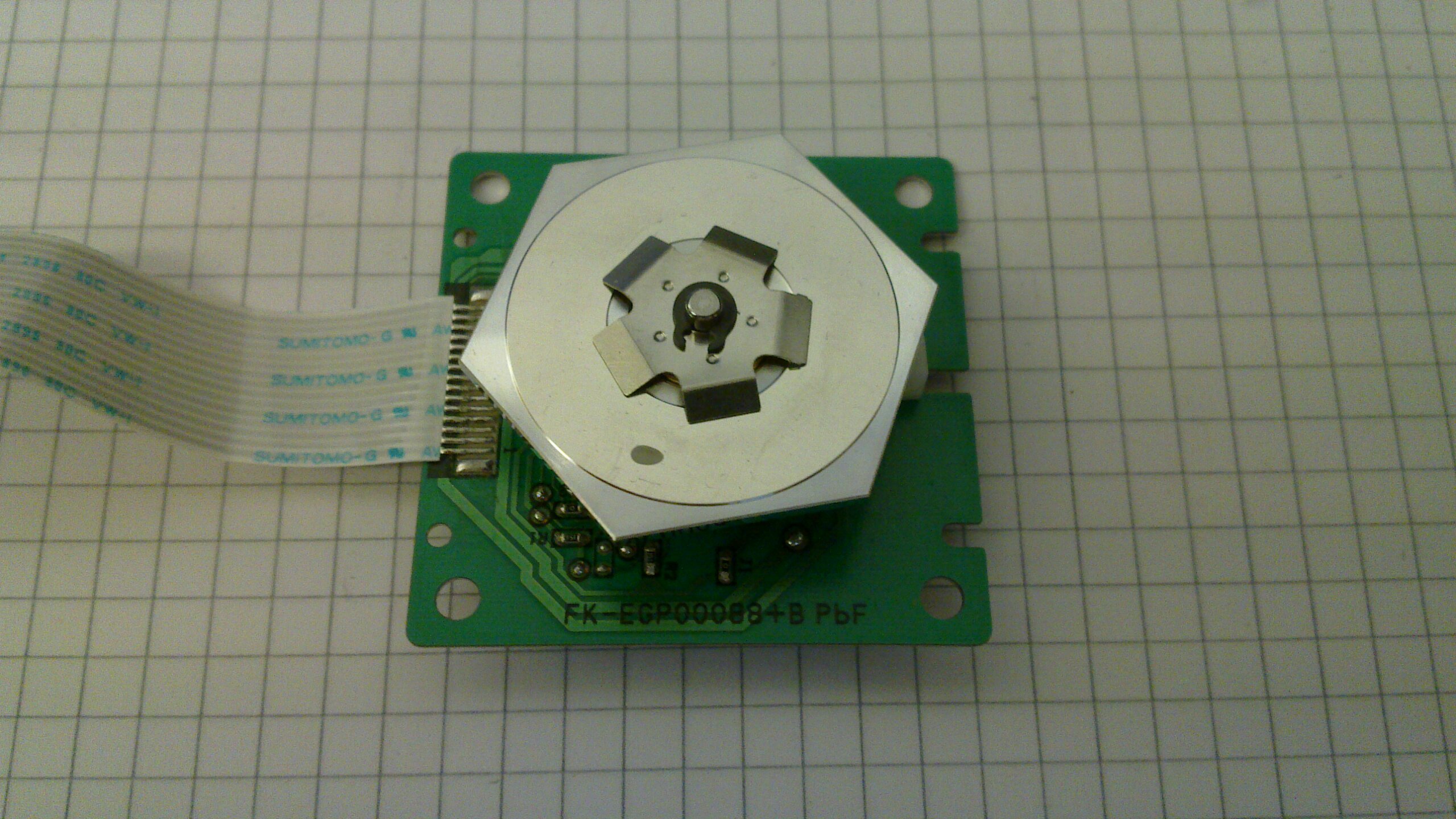
This is the unmounted galvanometer. I did the mistake and tried to remove the lock ring, but after i was succeed, i realized that this ring just held the mirror on the rotating part of the motor. The only thing i had to do to get the rotor off, was to turn the small white plastic hook.
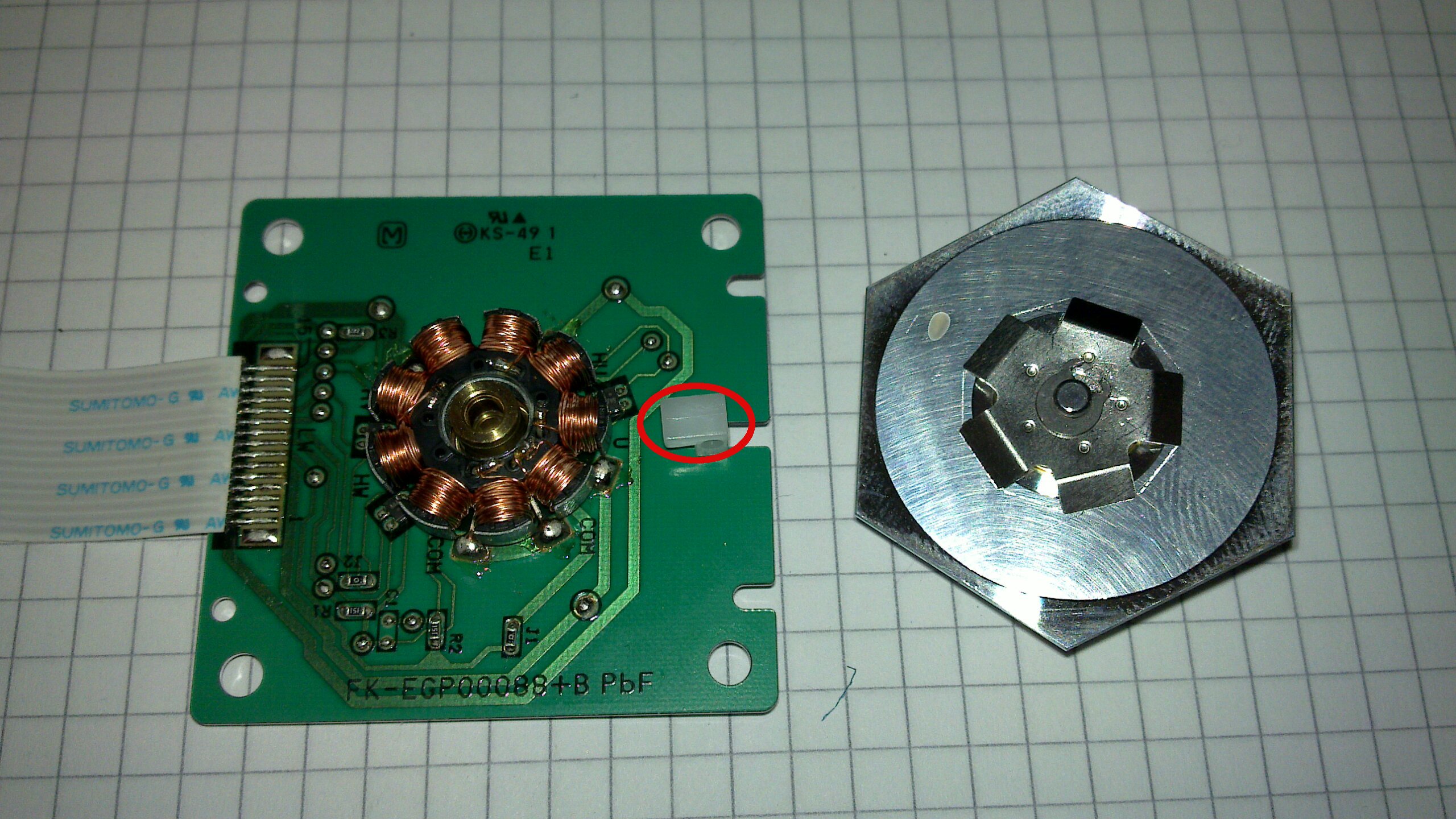
The disassembled galvo. Here you can see the white plastic hook i mentioned before.
I tried to get a schematic from the pcb to understand the functionality.
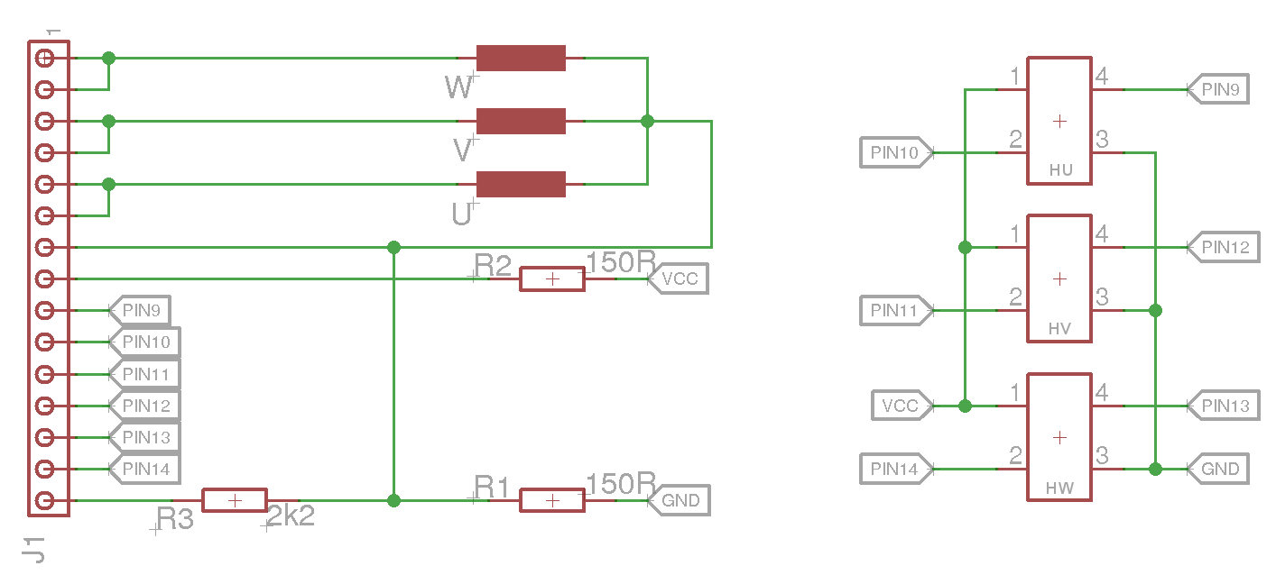
The schematic shows the 3 coils of the motor. There are 9 coils, 3 for each phase, but i can not see how they are connected together, so i drew just 1 for each phase. The 3 little devices with 4 legs each, are the Hall Sensors . The driver needs them to measure the actual position of the rotor.
If i have time, I’ll try to build a BLDC controller for this motor.