I own a Hörmann sectional door to my garage which is driven by a Hörmann SupraMatic E. To control the door via a home automation system you have several options:
- Connect potential free contacts directly to the motor. That means you have just very basic control over the motor because you can’t give up and down command but just a go command as you can with the radio controls.
- Usa a UAP1, a small extension box to have better control over the motor and get some feedback signals. Costs are about 50€ for the UAP1 and still a couple of potential free contacts are needed to connect the UAP1 to the home automation system.
- Speak directly to the motor and get the signals directly onto the homeautomation system. Exactly what I want to have :-)
I searched the internet for information about the bus, but little to nothing can be found about it. So I decided to reverse engeneer and document the bus!
Hardware 🔗
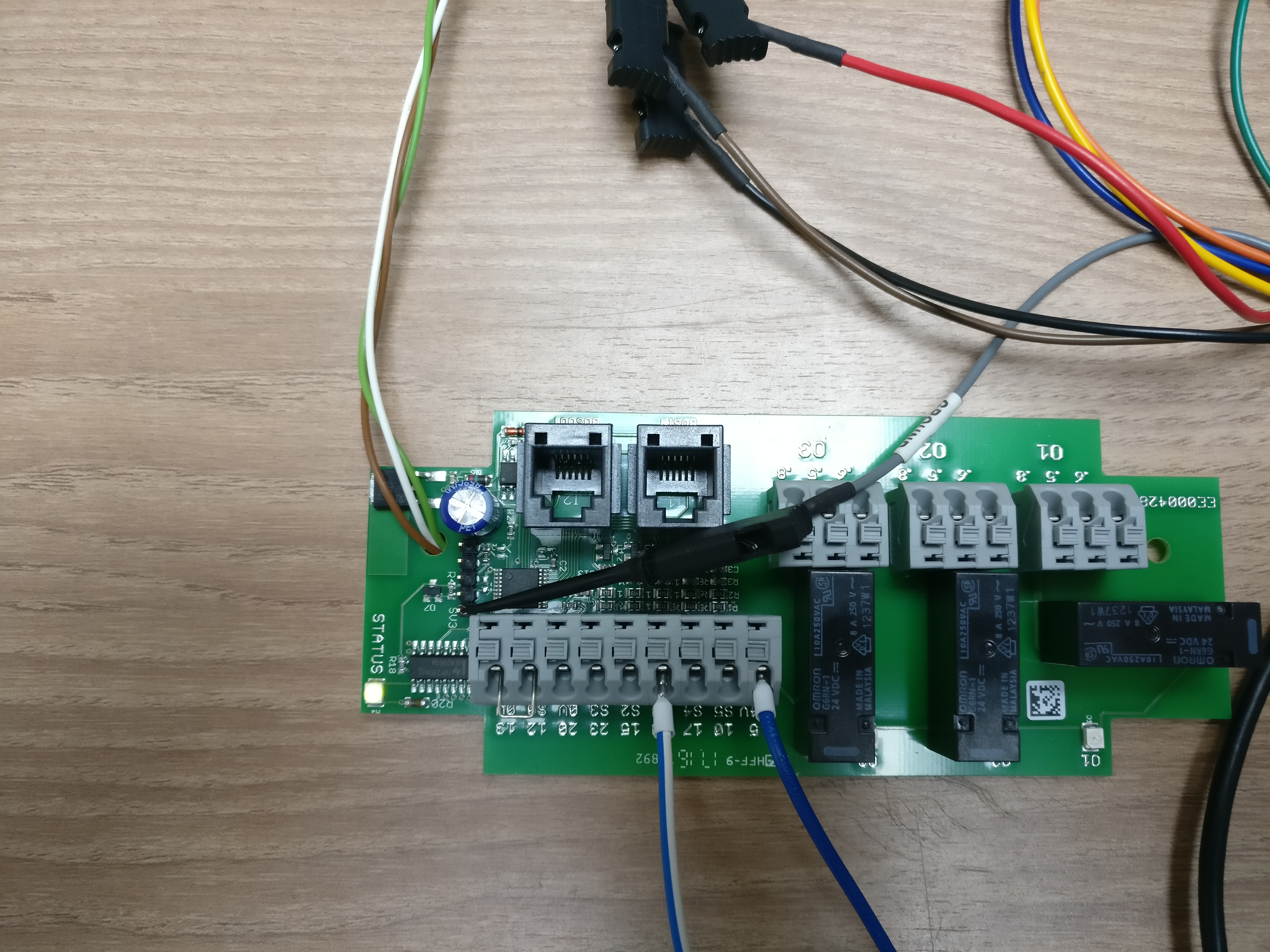
Top side of the circuit board:
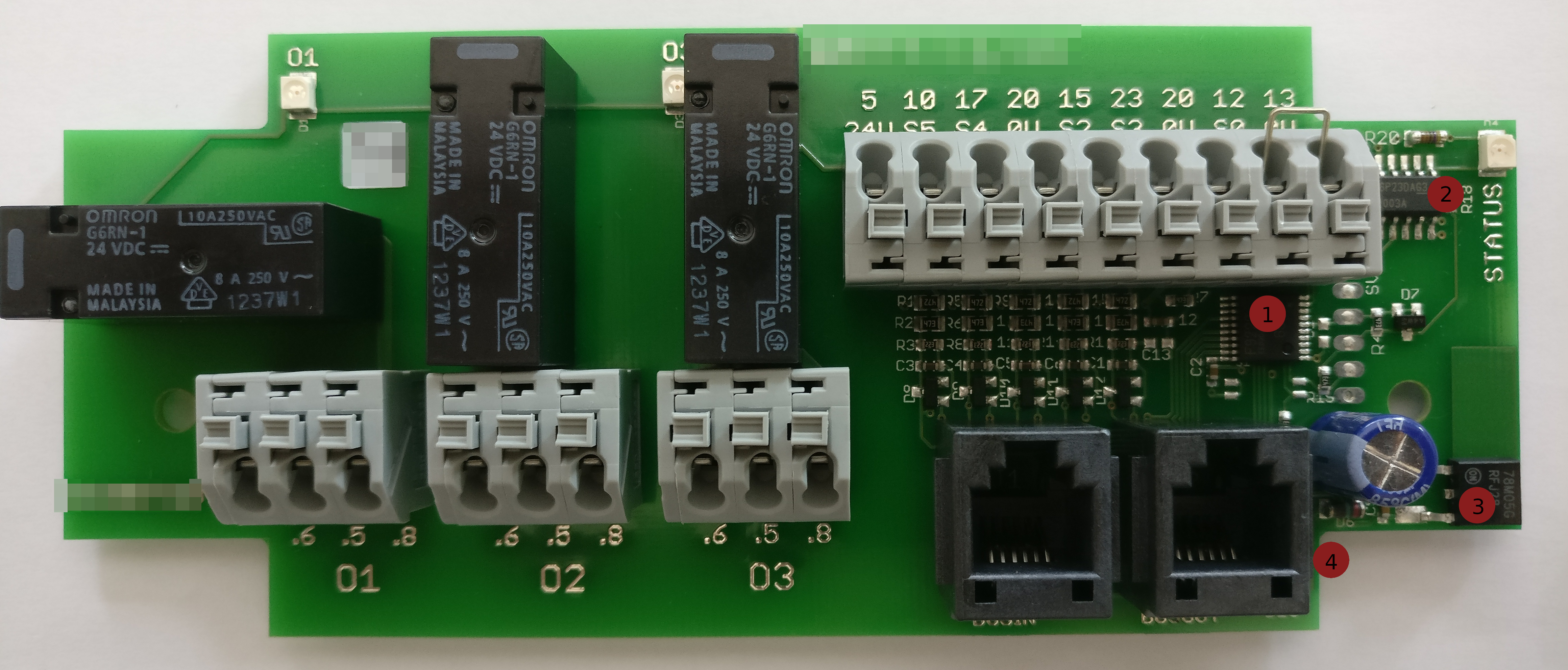
- The micro controller, a 20-pin SSOP, labled with F9222. After a while I found out that it must be a Renesas μPD78F9222 8-bit micro controller ( datasheet ).
- A Darlington Transistor Array, a 16-pin SOT, labled with ULN2003A. Drives at least the three relais, maybe more.
- The power supply, a D-PAK, labled with 78M05G. Converts the 24VDC coming from the motor down to 5VDC.
- A RS485 transceiver, a 8-pin SOT, labled with SP485EE.
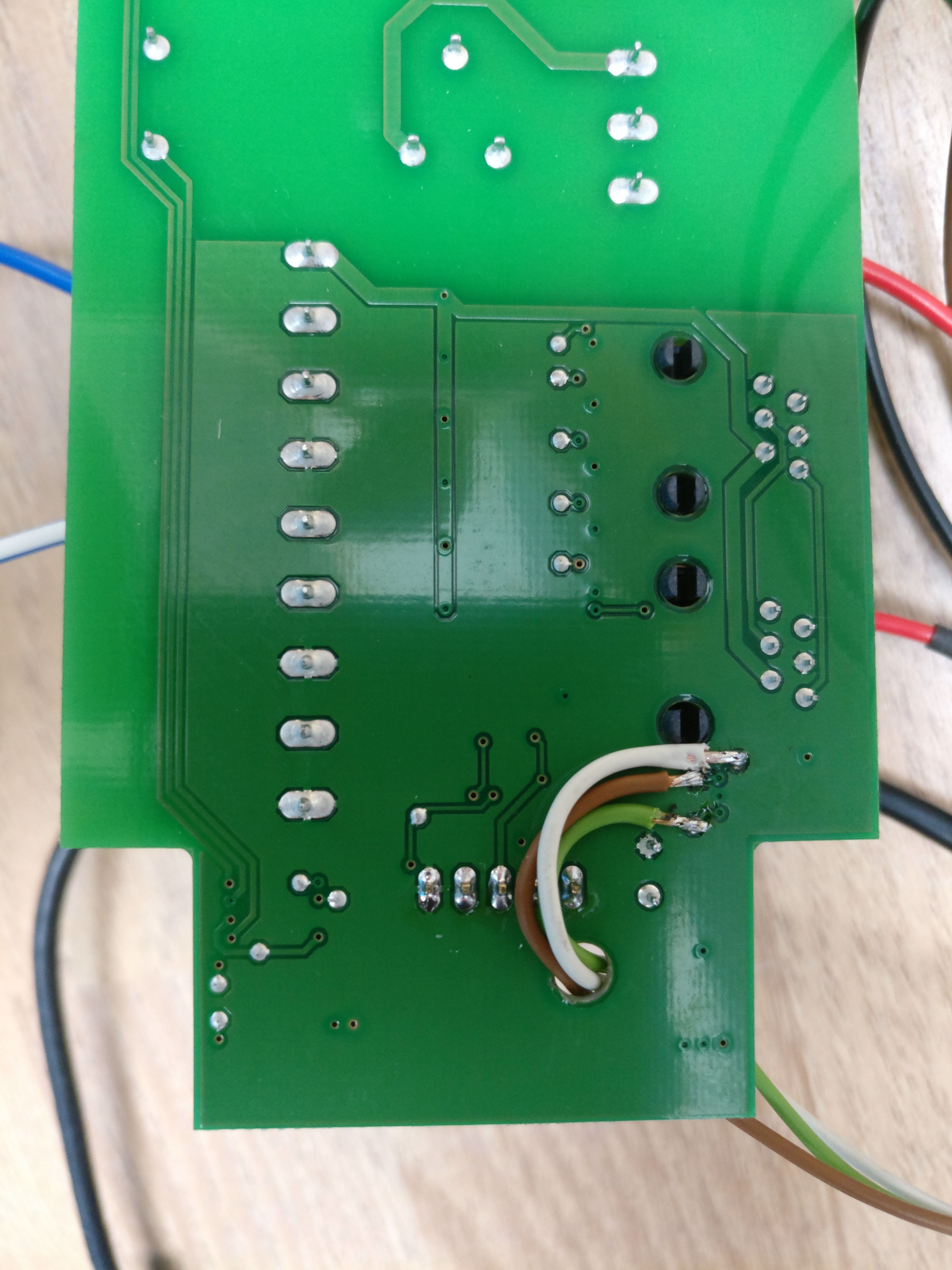
Bottom side of the circuit board:
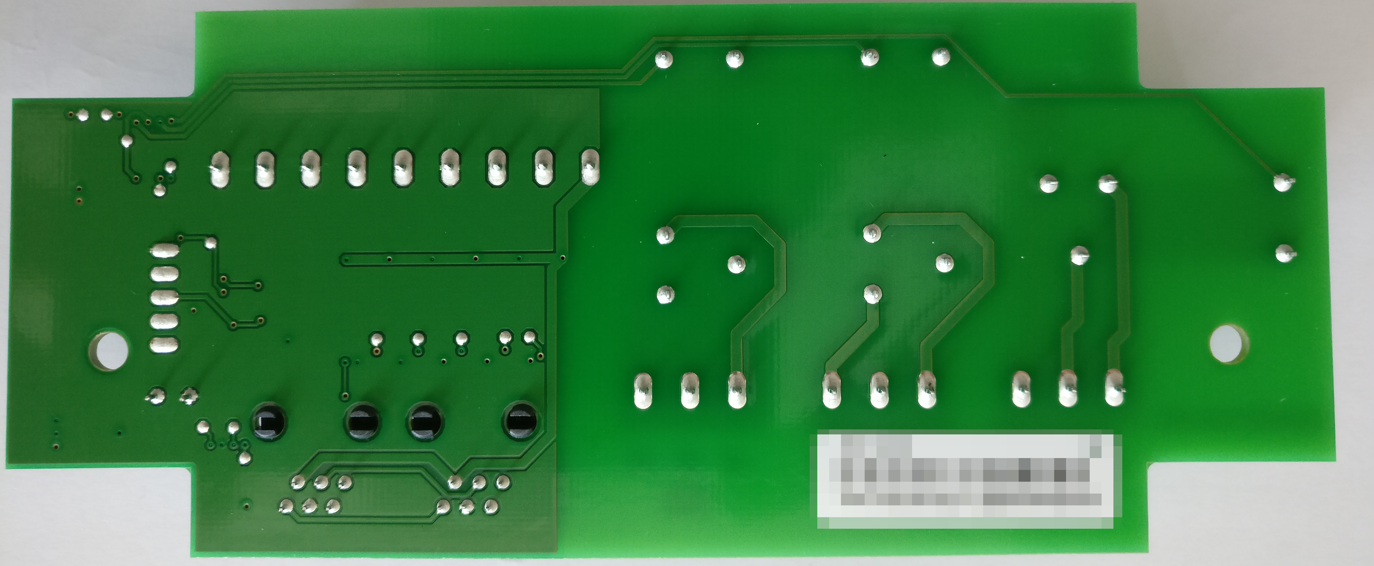
Not much to see here, just that all pins of the 6-pin RJ12 sockets are directly conected to each other.
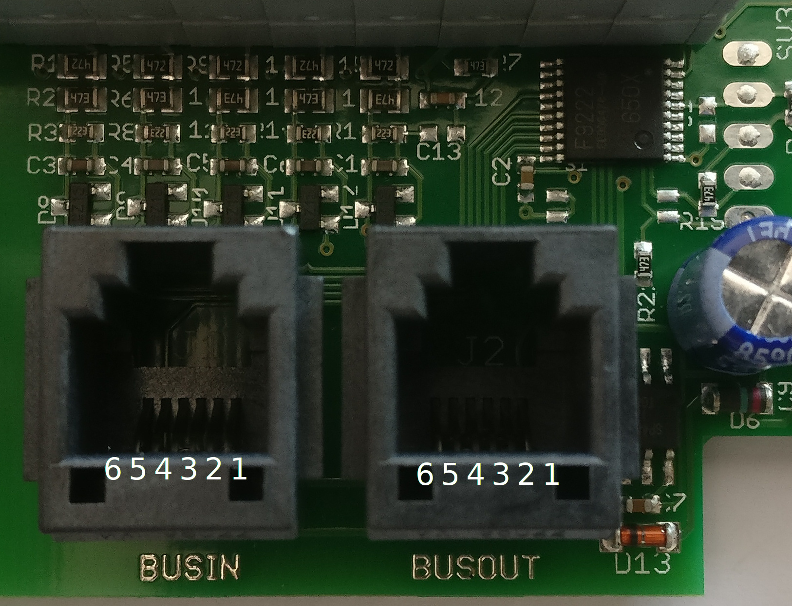
Pinout:
- Not clear
- 24VDC
- GND
- Not clear
- RS485, DATA-
- RS485, DATA+
I use a ExSys USB to RS422/RS485 converter I had lying around which a connected to the BUSOUT connector using a cable I made specifically for that purpose.
Reverse engeneering the protocoll 🔗
I expected a rather simple protocoll where no comunication happens until the UAP1 gets triggered by a switch, but I was more than wrong. Here’s what I got using the USB converter with the door closed idling:
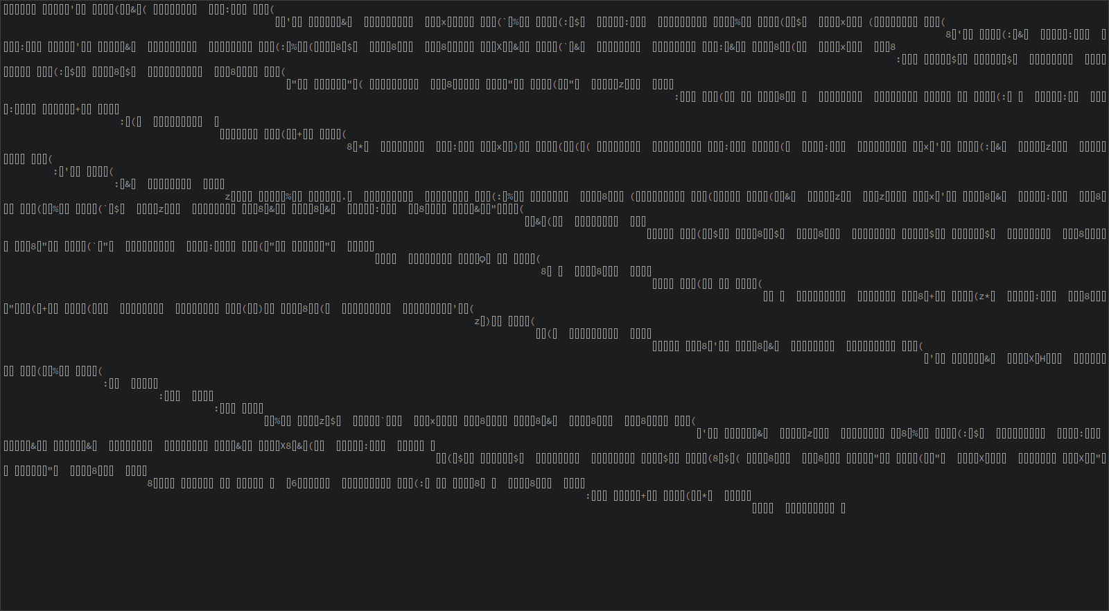
At first I thought I had a wrong baudrate but after a while I saw that at powerup the UAP1 sends the string “EE000478-00” before the gibberish starts. That occured at 19200 baud (8N1) so I think that must be the correct baudrate.
Then I encountered another problem I didn’t think about in the first place. RS485 is Half-Duplex, that means that only one participant on the bus can talk at a given time. But how can I tell who is sending which bytes!?
I had to go to the other side of the RS485 converter IC which is connected to the UART of the μPD78F9222 and one pin that enables the transmitter. Whith that one I can tell when the UAP1 is sending and when it is receiving! But connecting a SOT IC to the Logic analyzer is no fun, so I decided to solder three wires to the bottom of the PCB where the three signals I need are luckily connected to vias.
I also soldered a pin header to the 5 solderpads next to the μPD78F9222. I hoped to find the signals there as well but it turned out that is not the case. But at least I can connect to GND there. I decided to look at the boards communications without the motor connected. To supply the board with 24VDC, which normally comes in via the RJ12 connector, I simply used the terminals taht normally connect the switches.
My setup:
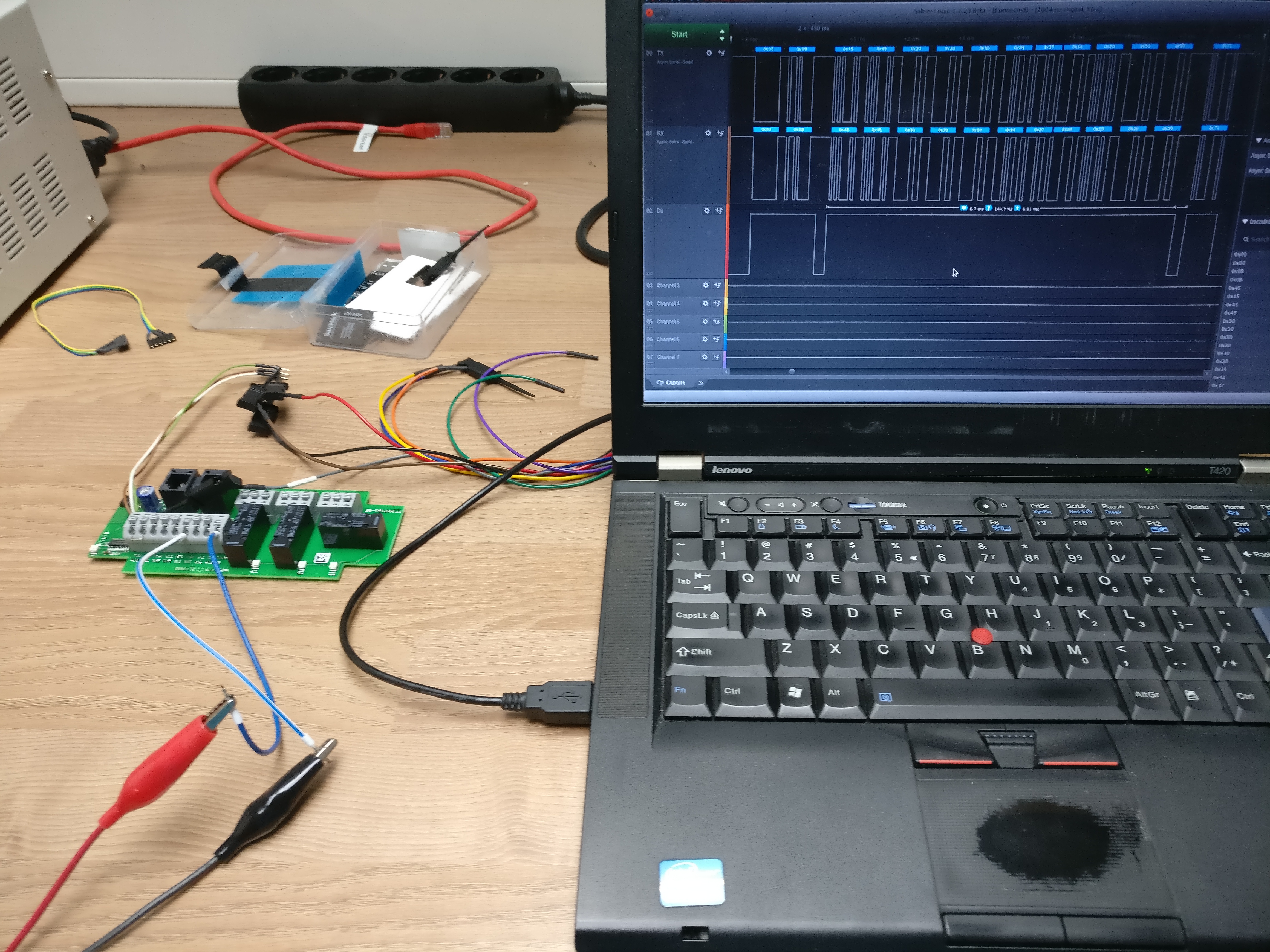
- White: TX
- Brown: TX enable
- Green: RX
When the board is powered while the logic analyzer is collecting data, we see these bytes comming in:
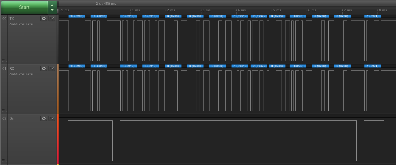
Thats 0x00 0x0B followed by the ASCII “EE000478-00” and terminated by 0x71.
At that point I realized that “EE000478-00” is printed to the PCB, so its kind of a model or serial number.
Unfortunately no other communication is happening when I trigger a “close door” for example.
It seems that this must happen when the UAP1 is connected to the motor.
Later I captured traces using my logic analyzer for each possible command, these are:
- startup (not a real command but maybe interesting)
- open door
- close door
- ventilation position
- toggle lamp
- Radio door open
- Radio door close
This is what I got:
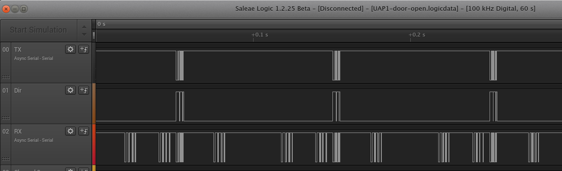
I’ve set two analyzers for async serial data on both, the RX and the TX line. They make me able to export the analyzed data as CSV.
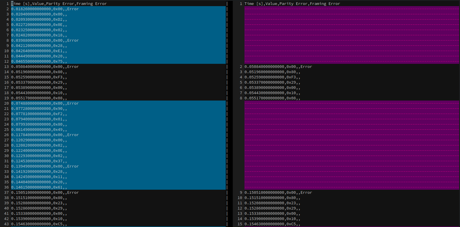
The RX line still contains the sent bytes of the UAP1, so I wrote a python Script that annotates the RX file with RX and TX labels.
** This is how far i got until now. I’ll try to extend this artcle or write a followup in the future. **
Update: 2018-12-18
Decoding the Messages 🔗
Someone from Italy contacted me after reading this article and pointed out to me that I might find helpful Information on the Hörmann protocoll in one of their numerous patents, and indeed they were ver helpful!
- https://patents.google.com/patent/WO2005076529A1/en
- https://patents.google.com/patent/US20130159573/en
The description in the patents is not cristal clear (at least to me) but still extremely helpful in figureing out whats going on on the bus.
A message is always formed like this:
0x8D 0x32 0x01 0x80 0xBC
-
The first byte
0x8Dis the address of the device this message is for -
The second byte
0x02is a combination of of a counter and a length. -
0x32 >> 4 = 0x03The counter is 3, it can only go as high a0x0Fand then flips over and begins at 0 again -
0x32 & 0x0F = 0x02This is the length of what I call the body of the message and means that two more bytes will follow -
The body consists of
0x01 0x80, I’ll come back to the meaning of the messages later -
The last byte
0xBCis a CRC8 checksum.
The CRC checksum 🔗
After being able to seperate the byte stream into messages, I still
wasn’t able to calculate the checksum. No common CRC8 generator gave me
the same result as the messages have.
I tried some CRC brute force attempts but without success. After having
discussed that issue with my Italian friend he was able to figure out
the polynom 0x07 as well as the initial value 0xF3 for the CRC algorithm.
I used the CRC calculator from sunshine2k.de > to verify the poly and init values. Fortunately the page gives you a nice lookup table for the CRC values which I then used in my Python program to verify all the messages I’ve recorded so far.
Address Ranges 🔗
The patent gives a list of adresses for certain device categories:
- 0: Broadcast
- 1-15: Reserved
- 16-45: Intelligent contol panels
- 46-47: Not specified in the patent
- 48-79: Dynamically assigned by the master
- 80-100: Not specified in the patent
- 101-109: Slave drives
- 110-127: Reserved
- 128: Master drive
- 129-143: Intelligent controllers
- 144: Diagnostic device / PC
- 145-256: Reserved
Messages 🔗
These are the messages I was able to make sense of so far. I might misinterprete some of them at this point :-) As I’ve described the message format above, I’ll only describe the body for the commands.
Bus scan 🔗
At startup the Master scans the bus for devices. In my case it starts at address 0x8D which is 141 in decimal.
It decrements this address and scans the entire bus. Why it doesnt scan the adresses 144 down to 142? No idea :-)
0x28 0x02 0x01 0x80 0x0D
0x01Slave query command0x80Master address
Slave scan reply 🔗
If a device is queried by the master during the scan, it answers with its type code.
In my case the UAP1 answers:
0x80 0x12 0x14 0x28 0xA7
0x14(decimal20) seems to be the device type. Unfortunately the patent doesn’t say anything about the device codes.0x28(decimal40) seems to be the device address.
Broadcast status 🔗
From the beginning the master sends a broadcast status message.
0x00 0x12 0x01 0x02 0x56
-
0x01is the broadcast status command -
0x02(binary00000010) is a bitwise representation of the status -
Bit 0:
0x02 & 0x01 = 0x00: End position open = False -
Bit 1:
0x02 & 0x02 = 0x02: End position closed = True -
Bit 2:
0x02 & 0x04 = 0x00: Option relay on = False -
Bit 3:
0x02 & 0x08 = 0x00: Light relay on = False -
Bit 4:
0x02 & 0x10 = 0x00: Error pending = False -
Bit 5:
0x02 & 0x20 = 0x00: Moving towards closed position = False -
Bit 6:
0x02 & 0x40 = 0x00: Moving towards open position = False -
Bit 7:
0x02 & 0x80 = 0x00: Burglar alarm = False
Slave status request 🔗
The master requests the status of all slaves it found on the bus periodically.
0x28 0x51 0x20 0x3A
0x20(decimal 32) is the request for the slave status
Slave status response 🔗
The slave responds to a status request by the master. The message can be between 1 and 3 bytes long and the patent states that it can be expanded. Furthermore I’ve only see this reply all the time.
** Attention: even as the patent gives a list with the meaning of the bits, the result seems odd to me!**
0x80 0x63 0x29 0x00 0x10 0x5E
0x29 (decimal 41) command for slave status
0x00 (binary 0000000 ) First status byte
- Bit 0: Impulse open = False
- Bit 1: Impulse close = False
- Bit 2: Impulse follow-up control = False
- Bit 3: Impulse pedestrian door = False
- Bit 4: Impulse vacation mode = False
- Bit 5: Impulse interior lights = False
- Bit 6: Impulse exterior lights = False
- Bit 7: Impulse half open = False
0x10 (binary 00010000 ) Second status byte
- Bit 0: End position / moving direction open = False
- Bit 1: End position / moving direction close = False
- Bit 2: Moving = False
- Bit 3: Error = False
- Bit 4: Reversing = True
- Bit 5: Not teached = False
- Bit 6: Light barrier error = False
- Bit 7: closing edge safety device error = False
The meaning of the third byte as listed in the patent is as follows:
- Bit 0: Light on
- Bit 1: Radio control getting teached
- Bit 2: Option relay on
- Bit 3: Quiescent current circuit open
- Bit 4: Not referenced
- Bit 5: Pedestrian door
- Bit 6: Learning button assignment
- Bit 7: Burglar alarm
As you can see the only status bit set, is from the second byte and means reversing according to the patent which makes no sense to me.
To dig deaper into the protocoll I need more data. Therefore I plan to hook up the bus to a network outlet I have in my garage that leads all the way down into my basement where my network rack sits. From there I’ll hook up the RS458 wires throug a USB to RS485 converter to my homeserver. That way I’m able to trace the bus in realtime without the need to leave the house (It’s pretty cold outside at this time of the year ;-)). I can contol at least the open and close commands throug my KNX installation which I already hooked up to the UAP1 a while ago.